Compressed
Hydrogen Storage

According to Figure 1, Hydrogen can be stored in the four types of pressure vessels. The ultimate application determines the storage option, which necessitates a trade-off between technical performance and affordability. Type I tanks with a pressure range of 150 to 300 bar (often 200 bar) are used to store H2 as an industrial gas. These are currently the most widely used and least expensive high-pressure containers. The type II tanks are preferred only when higher pressures are needed, which is typically for fixed applications. The type III and type IV vessels are made for portable applications where weight reduction is crucial. These vessels, however, cost a lot more money.

Figure 1: Pressure Vessel Types
Design and Manufacturing
For all pressure vessels, the design must take into account the service and test pressures, the user-specific external stresses (such as impacts, aggressive media, vibrations, the service temperature, and the weight of connectors), the actual lifetime (cycling), and the safety coefficients established for both static and dynamic conditions. The design also takes into account the failure modes, such as plastic deformation, buckling, creeping, fatigue metals, delaminations, fibre ruptures, fractures, ageing, etc.
Composites are also taken into consideration. The mechanical design and the selection of materials are determined by all these factors. When in touch with the gas, the materials must also be compatible. It's critical to understand the differences between metallic and composite vessels:
-
The mechanical properties of the composite are focused in the direction of the fibres, whereas the mechanical properties of the metal are anisotropic and isotropic, respectively.
-
The failure modes are different.
-
Ageing is different
The metallic or polymeric liner is hoop-wrapped or completely wrapped in the composite for all composite vessels using a filament winding machine. There are three different wrappings for cylinder vessels: hoop, polar, and helical. Types II only have hoop wrapping. The hoop and polar wrapping are typically combined in type III and type IV vessels, though any combination of the three wrappings can be taken into consideration. The same winding machine, fitted with several twisted heads, can wrap many containers. The resin needs to cure after being applied to the liner. Typically, the curing is done in heat-treated ovens that are suitable for the resin.
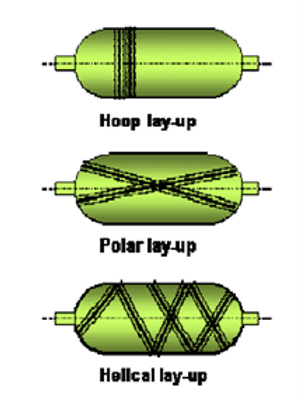
Figure 2: Pressure Vessel Design
Materials for high-pressure storage
The main problems with material compatibility for the high-pressure hydrogen vessels are:
-
The possibility of hydrogen atoms trapping and dissolving in steel due to this phenomena causes an early steel crack (stress corrosion cracking). The tank bursting is the biggest danger. Then, the 200 bar cylinder-based preventative guidelines were established.
-
The polymeric liner is graded for permeability. All gases that come into contact with polymers experience the penetration, which is unique to type IV vessels. It happens as a result of the diffusion and H2 gas dissolution in the polymer matrix. Low permeability polymers are one research area, and it was discovered at the outset of composite vessel development. H2 is a tiny molecule, which enhances the diffusion and subsequently the penetration. The penetration must be reduced to a particular rate for safety reasons. It results in the creation of unique polymers appropriate for hydrogen liners. For type IV hydrogen energy tanks, polyethene and polyamide (particular semi-crystalline grades) are most frequently utilised as liners. Another occurrence to watch out for is liner collapse or blistering, which happens when hydrogen gets trapped between the liner and the composite. Aluminium alloys don't specifically address any problems caused by hydrogen gas (with the exception of mercury). The high-pressure vessels are made out of the grades of aluminium alloy 6061 and 7000. They are utilised for type I, type II, and type III vessels as well as the metallic boss of type IV tanks and are not H2 specific. The effect of tap water, which dramatically reduces pressure cycle life, is the sole common problem for AA 6061 liners. The permeability is improved, whether using glass or aramid. The penetration must be reduced to a particular rate for safety reasons. It results in the creation of unique polymers appropriate for hydrogen liners. For type IV hydrogen energy tanks, polyethene and polyamide (particular semi-crystalline grades) are most frequently utilised as liners. Another occurrence to watch out for is liner collapse or blistering, which happens when hydrogen gets trapped between the liner and the composite. Aluminium alloys don't specifically address any problems caused by hydrogen gas (with the exception of mercury). The high-pressure vessels are made out of the grades of aluminium alloy 6061 and 7000. They are utilised for type I, type II, and type III vessels as well as the metallic boss of type IV tanks and are not H2 specific. The effect of tap water, which dramatically reduces pressure cycle life, is the sole common problem for AA 6061 liners. Tanks made of composite materials can be wrapped in leather, glass, aramide, or carbon fibres. These fibres are distinguished by their tensile strength, elongation, and tensile modulus. The typical ranges of these mechanical properties are shown in Table 1 for each category of fibre. For hydrogen energy applications, hydrogen is stored in high-pressure tanks (service pressure 350 bar). Consequently, carbon fibre is favoured from a mechanical standpoint. The same is true for different resins, such as polyester, epoxy, and phenolic. Epoxy resin, however, is the material most frequently used for pressure vessels due to its great mechanical qualities and strong durability. Commercially accessible pre-impregnated fibres are pricey. The thread is therefore impregnated just prior to the winding step, primarily for financial reasons.
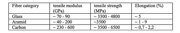
Table 1: Mechancial Properties for each Fibre Category
In conclusion, when storing hydrogen, special consideration must be given to the selection of steel for tanks of kinds I, II, and III, as well as the polymer for tanks of type IV. Low embrittlement often calls for tensile, disc, and fracture mechanism testing on the material. To demonstrate that permeation on one vessel is less than a predetermined rate (1 cm3/l/h), a thorough measurement of permeation is necessary. The penetration rate could also be determined solely by measuring a sample.
Liquid Hydrogen Storage (Cryogenic conditions)
For more than 40 years, industrial and medicinal gases have been frequently stored and transported in cryogenic tanks. The benefit of storing gases in this way is obvious: approximately 800 litres of petrol may be kept in a volume of 1 litre of liquid. When compared to compressed gas transportation, which is currently done at pressures of 200–300 bar (less gas per volume unit) and necessitates strong walls (and heavy containers) to resist the high pressure, this provides a considerable advantage.
Types of Cryogenic Vessels
The type of insulation utilised or the kind of applications can be used to distinguish between different types of cryogenic containers.
Cryogenic vessels, for instance, are typically vacuum insulated and made up of an outer protective jacket and an interior pressure vessel used for gases that need low temperatures to liquefy them. Perlite (a powder structure) or super insulation (layers of aluminium film wrapping) are used to lower the heat conductivity of the area between the inner vessel and the outside jacket. For gases like carbon dioxide or nitrous dioxide, non-vacuum insulated tanks are utilised because of the comparatively high liquefaction temperature. A thick covering of polyurethane is typically used for the vessels' insulation. Gases are stored in some cryogenic tanks at the production site and in others at the end-user site.
Reducing Wall thickness
In North America and Japan, contemporary techniques like "cold stretching" and "use of cold properties" are still not totally recognised. The wall thickness of the stationary cryogenic tanks is significantly reduced by these contemporary design and production techniques. It is a common practise in Europe to reduce the cost of cryogenic vessels by utilising fewer expensive components (such stainless steel).
Material Issues
Hydrogen embrittlement (HE)
HE effect is generally attained at ambient temperatures (see Fig. 9) and can often be neglected for temperatures above +100°C. In the case of unstable austenitic stainless steels commonly used for cryogenic vessels, the maximum HE effect is attained at -100°C but can be neglected for temperatures below -150°C. Figure 3 shows the properties of HE.
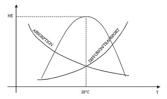
Figure 3: HE Properties
Compatibility of metals and alloys with low temperature
The use of metal at low temperatures entails special problems which must be resolved. Consideration must be given, in particular, to changes in mechanical characteristics, expansion and contractions phenomena and the thermal conduction of the various materials. However, the most important matter to be considered is certainly that of brittleness, which can affect certain metallic items of equipment when they are used at cryogenic temperature. In what follows, we shall only deal with ferritic steels, stainless steels and aluminium alloys, which are the main materials used at low temperatures. Generally, for metallic materials, ductility (characterized by elongation or constriction), and toughness (characterized by impact strength, notch effect strength or crack growth resistance) decrease when temperature is lowered. In the case of ferritic or martensitic steels, toughness drops rather suddenly in a relatively narrow temperature range; the failure mode, which was ductile, becomes brittle.
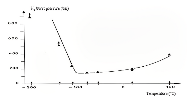
Figure 4: H2 burst pressure VS Temperature
Various types of tests are used to characterize the brittleness of materials due to cold. The most commonly used is the Charpy impact test. This test consists of breaking with an impact testing machine, under well defined conditions. From the test, the absorbed energy is determined, from which strength is calculated. These tests are carried out at different temperatures. Down to -196°C, they can be performed after immersion of the test pieces in a bath set at the desired temperature to bring them to that temperature. The test piece is then rapidly put on the pendulum ram impact testing machine for rupture, while respecting tolerances stipulated in the standards (plus or minus 2°C). For tests performed at lower temperatures, in particular at the temperature of liquid hydrogen or helium, it is necessary to use test pieces « bound » with a special insulation and to monitor the rise in temperature during the impact strength test after impression in an appropriate bath.
Contraction-Thermal Conduction
It is important to consider relative contractions due to a lowering of temperature, in particular for assemblies made of different materials. As an example, it can be seen that the main employed stainless steels contract inappreciably the same way. In addition, consideration is to be given to the possible transmission of cold by metal parts which are not brittle, while taking into account the thermal conductivity of materials and their specific heat, to parts, whether or not metallic, which are, for their part, brittle at low temperature. To avoid this, appropriate insulation is used.
In conclusion, and as regards cryogenic equipment, materials which are not brittle at minimum operating temperature should be used (nickel ferritic steels down to -200°C or stabilized austenitic steels and aluminium alloys which can be used down to absolute zero). In the case of materials known not to be brittle when cold, care is nevertheless to be taken with respect to their chemical composition, their heat treatment and their welding [1].
The group one, two and three light elements (e.g. Li, Mg, B, Al) build a large variety of metal–hydrogen complexes. They are especially interesting because of their light weight and the number of hydrogen atoms per metal atom. The main difference of the complex hydrides and metallic hydrides is the transition to an ionic or covalent compound of the metals upon hydrogen absorption. The hydrogen in the complex hydrides is often located in the corners of a tetrahedron with boron or aluminium in the centre. The negative charge of the anion, [BH4]− and [AlH4]−, is compensated by a cation, e.g. Li or Na. The hydride complexes of borane, the tetrahydroborates M(BH4), and of alane the tetrahydro aluminate M(AlH4) are interesting storage materials; however, they are known to be stable and decompose only at elevated temperatures and often above the melting point of the complex.
The stability of metal tetrahydroborides has been discussed in relation to their percentage ionic character, and those compounds with less ionic character than diborane are expected to be highly unstable. Steric effects have also been suggested to be important in some compounds. The special feature exhibited by the covalent metal hydroborides is that the hydroboride group is bonded to the metal atom by bridging hydrogen atoms similar to the bonding in diborane, which may be regarded as the simplest of the so called “electron-deficient” molecules. Such molecules possess fewer electrons than those apparently required to fill all the bonding orbitals, based on the criterion that a normal bonding orbital involving two atoms contains two electrons
The compound with the highest gravimetric hydrogen density at room temperature known today is LiBH4 (18 mass%). Therefore, this complex hydride could be the ideal hydrogen storage material. LiBH4 desorbs three of the four hydrogen in the compound upon melting at 280°C and decomposes into LiH and boron. The desorption process can be catalysed by adding SiO2 and significant thermal desorption was observed starting at 100°C. Recently it has been shown that the hydrogen desorption reaction is reversible and the end-products lithium hydride and boron absorb hydrogen at 690°C and 200 bar to form LiBH4. The scientific understanding of the mechanism of the thermal hydrogen desorption from LiBH4 and the absorption remains a challenge and more research work needs to be carried out. Very little is known yet about Al(BH4)3, a complex hydride with a very high gravimetric hydrogen density of 17 mass% and the highest known volumetric hydrogen density of 150 kg·m−3. Furthermore, Al(BH4)3 has a melting point of −65°C and is liquid at room temperature. Besides the covalent hydrocarbons, this is the only liquid hydride at room temperature.
The complex hydrides represent a very interesting and challenging new hydrogen storage material. However, very little is known about the stability, the sorption kinetics and the reversibility, since most of the complex hydrides do not exist as intermetallic compounds when the hydrogen is removed [2].
Complex Hydrides
Comparative Analysis
A weighted average comparative study was conducted on the potential modes of hydrogen storage. We found compressed hydrogen storage as the most viable mode of storage as compared to liquified and material-based storage.
Rational
We had given CAPEX and utility requirements the highest weightage in deciding the storage type. Due to the need to maintain cryogenic conditions liquefied storage has high utility requirements and since the vessel operates at cryogenic conditions specialized materials have to be adopted which will increase the CAPEX. In the case of complex-based storage since the technology is immature it is not feasible to scale it up to an industrial level. However, it is worth noting that complex-based storage is the safest and will have potentially lower utility requirements. Therefore since compressed storage has an optimal utility requirement and is considered relatively safer than liquid storage we choose to go ahead with compressed storage.
References
[1] Barthélémy, H. (2012). Hydrogen storage – Industrial prospectives. International Journal of Hydrogen Energy, 37(22), pp.17364–17372. doi:https://doi.org/10.1016/j.ijhydene.2012.04.121.
[2] Züttel, A. (2004). Hydrogen storage methods. Naturwissenschaften, 91(4), pp.157–172. doi:https://doi.org/10.1007/s00114-004-0516-x.